Stop Start Motor Wiring Diagram
A wiring diagram is a simplified standard photographic representation of an electrical circuit. It reveals the components of the circuit as streamlined forms and the power and also signal links between the gadgets.
 Kitchen Wiring Diagram Blueprint Electrical Layout Electrical Wiring Electrical Plan
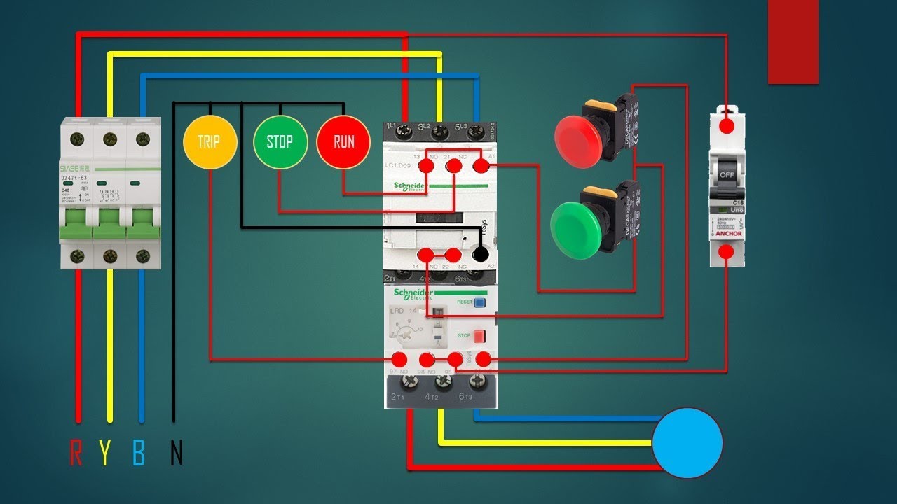
When you press the start button and the stop button.
Stop start motor wiring diagram. Pressing start immediately sends power through the start pushbutton and the seal in contacting energizing the coil. Otherwise the structure will not function as it ought to be. See image below for an example of 3 wire control being used to pull in a contactor to start a 3 phase motor.
There s a diagram shown in the process. Assortment of start stop wiring diagram motor. How to wire contactor and motor protection switch direct on line.
Single station with the starter. Each component should be set and linked to different parts in specific manner. This video guides you how the stop start motor control circuits wiring done.
With the switch closed the control circuit acts as a normal stop start station controlling a load connected to the pilot device power is sitting on the start and seal in terminals of the pushbutton. Push to make ptm switch use to start the motor and push to brake ptb switch use to stop the motor. Start stop control wiring diagrams.
Motor control circuits are effective way. Wiring diagram single motor with start stop switch basic control motor to get start or stop the motor use a push button switch as a trigger a motor. Wiring diagram single motor with start stop switch.
Motor starter wiring diagram start stop motor starter wiring diagram start stop every electrical arrangement is composed of various distinct pieces.
 12v To 110 220v Voltage Inverter Wiring Diagram And Flat Battery Wiring Diagram 12v 2 In 2020 Van Life Van Conversion Layout Motorhome
 Wiring Diagram Tutorial Standard Faroutride Electrical System Electrical Diagram Electricity
 Fj40 Wiring Diagrams Toyota Hiace Toyota Land Cruiser Fj40
 Yamaha Grizzly 350 Wiring Diagram Dolgular Diagram Yamaha Clymer
 Photocell Wiring With Contactor Diagram Electricity Wire
 Yamaha V Star 5 Engine Diagram Book In 2020 Electrical Wiring Diagram Klr 650 Electrical Diagram
 Kia Pregio Wiring Diagram Kia Pregio Aircon Wiring Diagram Wiring Diagram Fuse Box Car Fuses Pontiac Sunfire
 Wiring Diagram Slot Cars Slot Car Racing Slot Car Tracks
 Three Phase Dol Starter Control Overload Indicator And Power Wiring Di Electrical Circuit Diagram Electrical Jobs Electricity
 Design Home Wiring Wiring Diagram Detailedhome Wiring Plan Software Making Wiring Plans Easily Home Wirin House Wiring Home Electrical Wiring Electrical Layout
 Wiring Diagram For 220 Volt Single Phase Motor Bookingritzcarlton Info Electrical Circuit Diagram Ac Capacitor Circuit Diagram
 Wiring Diagram Plc Mitsubishi Bookingritzcarlton Info Ladder Logic Electronic Engineering Logic Programming
 The Post Explains A Simple Variable Frequency Drive Or Vfd Circuit Which Can Be Used For Driving All Circuit Diagram Electrical Wiring Diagram Power Inverters
 Epiphone Les Paul Wiring Diagram Stock Database And Chitarra Elettrica Chitarra Elettronica
 Riser Diagram In 2020 Electricity Electrical Engineering Engineering
 Simple To Read Wiring Diagram For A Boat Boat Wiring Electrical Wiring Diagram Electrical Diagram
 Contactor Wiring Guide For 3 Phase Motor With Circuit Breaker Overload Relay Nc No Swit Electrical Circuit Diagram Home Electrical Wiring Electrical Projects
 Septic Pump Float Switch Wiring Diagram Tank Fresh Amazing Gallery The Best Electrical Circuit 7 Septic Tank Float Electrical Installation
 Olympian Generator Wiring Diagram 4001e Collection In 2020 Transfer Switch Electrical Circuit Diagram Electrical Wiring Diagram

Comments
Post a Comment